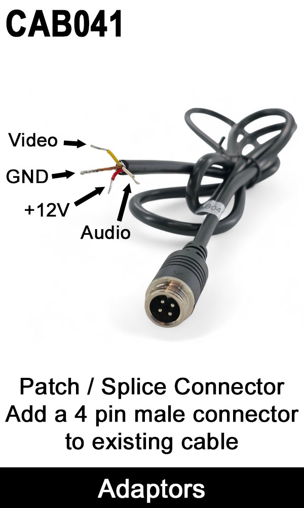
CAB041 - 4 Pin Male to bare wires - For soldering on to existing leads

Price

£3.60

VAT Included £0.60
Availability IN STOCK
Product Code: CAB041
Quantity
(from 1 to 2)

If you'd like this by

Order within ::

(Please select Next Day Delivery Option - Mainland UK only) Terms Apply

Description

We very often get people who have an older system that has unusual connectors that wish to adapt their existing wiring to the industry standard - 4 pin aviation connector. In the past, our customers used to purchase a 1M cable, which they would cut in half to connect each wire to their existing lead. We decided to get our cable factory to make us a new 100cm length lead which has been pre-separated out to the individual wires.

The red wire is for +12V power.

The twisted copper braiding is the earth - if your old video signal cable has twisted braiding around it this can be twisted together and soldered to this wire.

The white wire is for audio - most cameras don't have a microphone so this can be left unconnected in most cases.

The yellow wire is for video signal.

Instructions for adding this lead in to your existing wiring

If you don’t have a conventional plug and play connector then you will need to upgrade your connector to the more modern style used in cameras like ours.

Tools you will need:

  • Multimeter
  • Wire Cutter/Stripper
  • Insulation Tape or Heat Shrink
  • Soldering Iron
  • Soldering Gun
  • 1M 4 pin cable to bare wires (this listing)

Warning 1 : Never cut the wires to the new camera as this may allow atmospheric moisture to enter down the cable and wire colours will be different to advice on this page.

Warning 2 : Never cut the extension cable whilst there is power to the camera system as this may cause a short.

Method:

  1. Ensure power is dead to the system and cut the old connector off on the main extension wire (not the camera cable as this often has extra wires and no screening).
  2. Separate the wires out so they aren’t touching each other.
  3. Power up the system by turning the monitor on.
  4. Use your multimeter to determine which wire(s) carry power (usually just one - but occasionally more) and note the colour down (DO NOT ASSUME COLOURS FOLLOW CONVENTION - WE HAVE SEEN LOTS OF COLOURS USED FOR VARIOUS PURPOSES).
  5. Remove power to the system so that you can make your connections.
  6. Connect the red wire on our cable to the coloured wire you identified as +12V on your existing wiring (solder is the gold standard). (Positive power supply is the only wire that can cause damage if you get it around the wrong way so please be careful).
  7. With luck you will find a wire on your main extension cable that has shielding around it - this should be the video signal cable. Connect this with the video cable on the new lead (the yellow wire). The shielding from the old signal wire can be twisted together with your earthed cable shielding on the new cable. Insulate the connections made.
  8. If you power the system now you might find the camera works already (because a lot of systems link the earth screening up with the main earth in the connector - if it doesn't then you will need to identify the earth cable by touching the remaining spare wires in your old cable (ensure none are positive first) against the earth/screening on the new connection cable until you get a picture on the screen.
  9. If your camera has sound (we only stock a few that do) and if your monitor has a speaker then you can enable sound by attaching the white wire from our cable, you will need to touch it against the spare wires on your cable until you find one that is giving you audio.
  10. Tidy up your wiring ensuring all the wires are well soldered and insulated.
  11. Job done, time to put the kettle on.